This site contains affiliate links for which we may be compensated.
Bolt Pattern Cross Reference and Wheel Sizes
Interchangeable Rim Chart for 3 lug, 4 lug, 5 lug, 6 lug, 7 lug, 8 lug and 10 lug Bolt Patterns for Cars, Trucks, Station Wagons, Vans, SUVs, Motor Homes, ATVs and UTVs
Vehicles with 10 x 225 Bolt Pattern
![]() Bolt Pattern: 10 X 225
Bolt Pattern: 10 X 225
> Bolt Pattern Details and Matching Vehicles![]() OEM Wheel Size(s): 19.5 X 6
OEM Wheel Size(s): 19.5 X 6
Torque Sequence: 1, 6, 8, 4, 10, 2, 5, 7, 3, 9
 ATTENTION eBay and CraigsList Used Wheel Sellers: This is an excellent tool to assist you when selling wheels to display what vehicles your wheels will interchange with and vice versa. Simply display the rim bolt pattern and matching vehicles, Then Copy and Paste the URL into your listing - your potential buyers will easily determine if the wheels will fit their vehicle.
Jump to Manufacturer Bolt Patterns and Wheel Sizes
ATV / UTV / Power Sport Bolt Patterns:
Passenger Car / Truck Bolt Patterns:
Additional Wheel / Measurement Information
 Key Identifying Wheel Dimensions: Wheel Bolt or Lug Pattern (or bolt circle, lug circle, lug pattern, etc.) is the measured diameter of an imaginary circle formed by the centers of the wheel lugs or bolt holes. Bolt patterns can be 3, 4, 5, 6, 7, 8 or 10 lug holes. A bolt circle of 5 x 4.5 would indicate a 5 lug bolt pattern on a circle with a diameter of 4.5 inches.
Wheel Dimensions
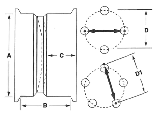
There are four important measurements that are used to categorize and identify a wheel for fitment purposes.

- Rim Diameter The actual diameter of the wheel at the point where the tire bead seats (NOT the outer lip of the rim).
- Rim Width Measure from the inside of the outer lip at the bead seating point to the inner lip.
- Back Spacing From the inside of the wheel at the point where it contacts the hub, brake drum or axle flange to the inside edge (lip) of the wheel.
- Bolt Pattern The measured diameter of an imaginary circle formed by the centers of the wheel lugs or bolt holes.
How To Measure Wheel Bolt Pattern
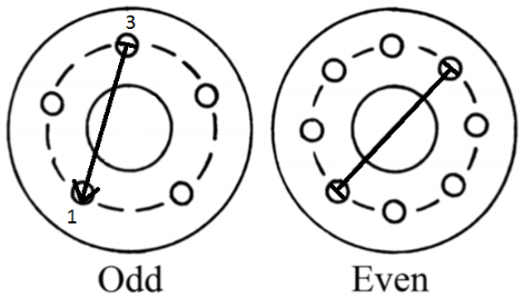
If there is an EVEN number of lugs: Measure center-to-center on lugs directly across from each other.
If there is an ODD number of lugs: Measure from the CENTER of one lug to the OUTER EDGE of the hole diagonally across from it.
Lug Nut Types

Common Bolt Pattern Conversions
This information is accurate to the best of our knowledge. No warranties or guarantees are expressed or implied as to the accuracy of the information provided on this site. Use of this site constitutes your agreement to these terms.
See Also:
- How to Measure Bolt Pattern Bolt pattern - diameter of an imaginary circle formed by the centers of the wheel lugs.
- Wheel Lug Nut / Bolt Torque Sequence Correct Wheel Lug Nut / Bolt Torque Sequence - 4 lug, 5 lug, 6 lug.
- How to Measure Wheel Back Spacing This measurement is important to be sure you have proper wheel clearance.
- How To Read A Tire Sidewall Learn to understand the common markings found on tire sidewalls.
- How To Plus Size Your Wheels
- Wheel, Tire and Fender Fitment Calculator Calculate Wheel Fitment, Tire Stretch and Rolling Radius. includes Speedometer Error Calculator. Play with specs, try different settings and combinations, compare results.
- Tire Size Change / Speedometer Calibration Calculator This calculator is designed to give information related to tire size changes and the general impact they have on the calibration of a speedometer. It determines speedometer error and tire size information based on published and generally accepted tire dimensions as given by the standard US tire system (i.e. 205/45-ZR16). All calculations are based on the assumption of a new tire (as opposed to used) where the numbers on the tire accurately represent the dimensions.

